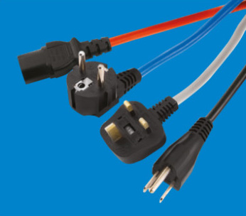
Testing requirements and USB socket-outlets
Are you having to deal with problems with USB socket-outlets that have been faulty following insulation resistance testing? If so, Jake Green, Head of Technical Engagement with Scolmore Group can shed some light on the issue.
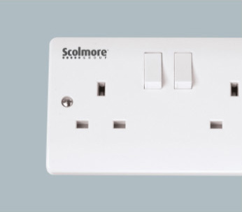
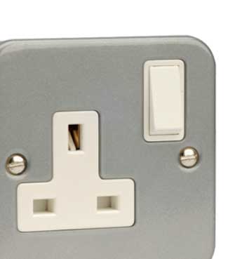
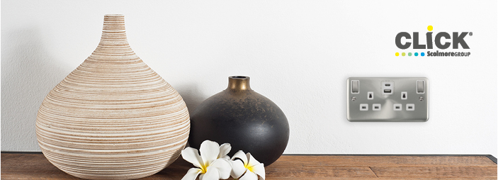
With USB socket-outlets, the charging unit is built into the back of the socket and this is sometimes fixed to the on position. This means that the switches on the socket that control the 13 amp plug element has no connection to the USB charging point, with the result that is permanently connected. This could cause problems when carrying out insulation resistance testing, as the electronic components of the USB charging unit are part of the circuit and therefore the 500V that electricians use to test them could damage those components resulting in a faulty charging port.
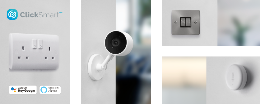
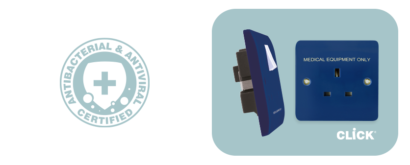
The Click range of USB sockets has been designed to withstand the 500V insulation test due to the nature of the circuitry built within the USB socket.
Chapter 64 of BS 7671 details the general requirements for initial verification, and Section 643 deals with the requirements for testing. Here we briefly consider the requirements for insulation resistance testing and the care that should be taken when testing after second fixing has occurred.
Insulation resistance testing
Insulation resistance testing is carried out to confirm that there are no inadvertent connections between live conductors, and between live conductors and Earth before the installation is energised (643.3.1).

The insulation resistance test is a ‘dead’ test, and typically the normal supply should not be ‘live’. To this end the person carrying out the test should ensure that the circuits to be tested are isolated and the normal power cannot be energised inadvertently.
The minimum required insulation resistance values in megohms is detailed in Table 64, although a value significantly in excess of these stated values is preferred (643.3.2).

Regulation 641.1 requires that every installation is tested both during erection and on completion before being put into service. Insofar as this relates to insulation resistance testing, this means that tests should be carried out after first fixing (after cables have been installed and prior to equipment being connected). This test confirms that the installed cables are in a fit state.
The final insulation resistance test needs to be carried out after second fixing has taken place. However, after second fixing it may be that connected equipment may influence the measurement or result of the test (643.3.3). Where this is the case, following the connection of equipment, it is permitted to reduce the test voltage to 250 V DC and to test between the live conductors (connected together) and Earth.
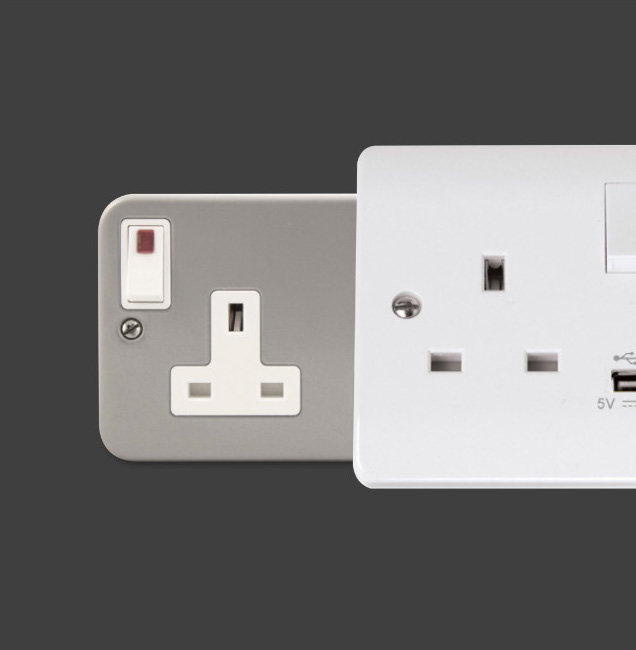
Sensitive electronic equipment
The note attached to Regulation 643.3.3 indicates that manufacturer’s instructions may recommend some equipment needs to be disconnected even when the test voltage is reduced to 250 V DC. This may apply, typically, to accessories such as socket-outlets with USB connections and the like.
Scolmore’s Click socket-outlets with USB ports do not require disconnecting and may be tested between live conductors (connected together) and Earth at a test voltage of 500 V DC whilst still connected in circuit.
Conclusion
Insulation resistance testing is an essential part of ensuring that prior to energisation the installation is safe. The tests verify that there are no inadvertent connections between live conductors and between live conductors and Earth. Care should be taken to ensure that any connected equipment is capable of withstanding the test voltages applied. Where there is a risk of damage or test results outside of the permitted range, it may be necessary to disconnect equipment prior to any test being carried out.
Upcoming Events
 Ovia Uk
 ESP
ESP
 Unicrimp
 Click Smart
 Scolmore Dubai
 Ovia Ireland
 Sangamo
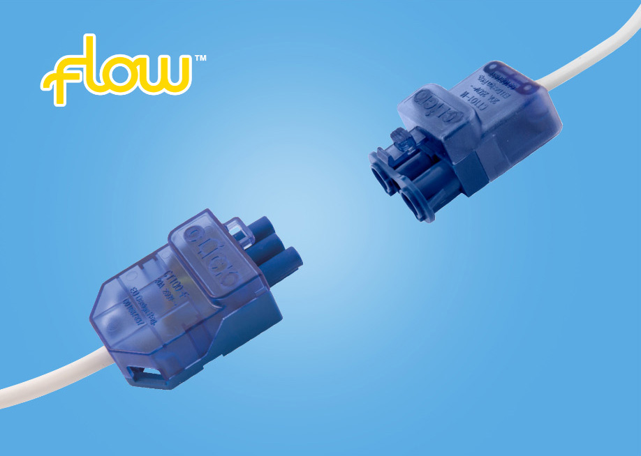
 IEC Lock
 Click Litehouse
 ESPi
ESPi